How to Perform a Residential Combustion Analysis: A Complete Guide to Heating Efficiency, Safety & Energy Audits
Published 9/4/2026
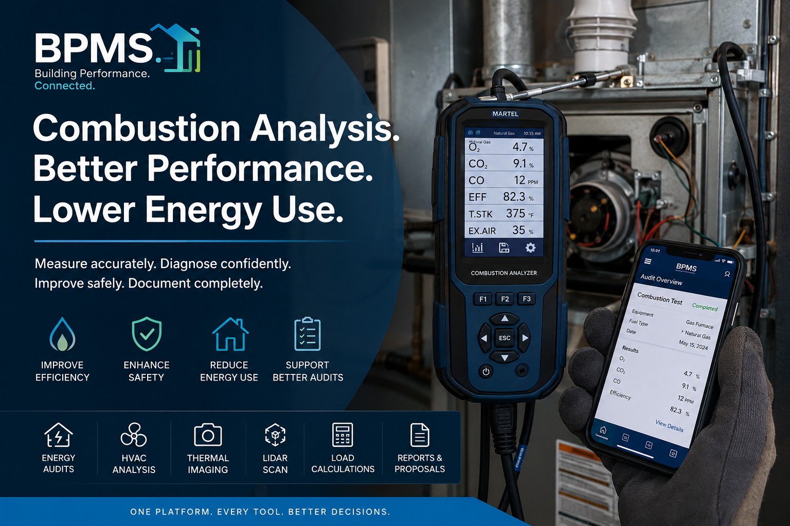
Learn how to perform a residential combustion analysis on furnaces and boilers, understand O₂, CO₂, carbon monoxide, stack temperature, draft, and combustion efficiency, identify conditions that may increase energy consumption, and incorporate combustion testing into a comprehensive home energy audit using BPMS™.
What Is Combustion Analysis?
A residential heating system does more than simply produce heat.
When a fuel-burning furnace or boiler operates, fuel and combustion air must be brought together under controlled conditions. The resulting combustion gases must then transfer heat effectively to the building while combustion products are safely vented from the structure.
Combustion analysis is the process of measuring and evaluating that combustion process.
Using a properly maintained and appropriate combustion analyzer along with other diagnostic procedures, a qualified technician can evaluate operating characteristics such as:
* Oxygen (O₂)
* Carbon dioxide (CO₂), often calculated by the analyzer
* Carbon monoxide (CO)
* Flue or stack temperature
* Combustion efficiency
* Excess air
* Draft, when measured with appropriate equipment
* Ambient carbon monoxide
* Other fuel- and analyzer-specific combustion parameters
These measurements can provide valuable information about how effectively a heating appliance is operating and whether conditions exist that require further investigation.
For an energy auditor, HVAC contractor, weatherization professional, or building-performance specialist, combustion analysis can therefore serve two important purposes:
Evaluate combustion-related safety conditions and understand heating-system performance.
That makes combustion analysis an important component of a comprehensive building-performance assessment when fuel-burning equipment is present.
⸻
Why Combustion Analysis Matters During an Energy Audit
A home energy audit should examine the building as a system.
The building enclosure affects heating and cooling loads.
Insulation affects heat transfer.
Air leakage affects infiltration.
Duct leakage can affect delivered HVAC performance.
Heating-system efficiency affects how much purchased fuel must be consumed to meet the building’s heating demand.
Combustion appliances add another consideration: they must operate and vent properly under the conditions in which they are installed.
This means an auditor should not look only at how much energy the building needs.
The auditor should also consider:
How effectively is the heating equipment converting purchased fuel into useful heat, and are there combustion or venting conditions that require attention by a qualified professional?
Combustion analysis helps provide evidence for answering that question.
⸻
Understanding the Combustion Process
Fuel combustion requires the correct relationship among fuel, oxygen, ignition, mixing, heat transfer, and venting.
In simplified terms, ideal combustion of a hydrocarbon fuel would convert the fuel and oxygen primarily into carbon dioxide, water vapor, and heat.
Real heating appliances do not operate under perfectly theoretical conditions.
They generally require excess combustion air to help achieve reliable combustion.
Too much excess air can reduce efficiency because additional air is heated and exhausted through the vent.
Too little combustion air or improper fuel-air mixing can contribute to incomplete combustion and potentially dangerous carbon monoxide production.
Poor burner condition, incorrect setup, restricted venting, inadequate combustion air, heat-exchanger problems, equipment deterioration, or other conditions may also affect measured combustion performance.
That is why combustion analysis should be based on actual measurements rather than flame appearance alone.
⸻
The Measurements That Matter
Oxygen — O₂
Oxygen remaining in the flue gas provides information about the amount of excess air involved in combustion.
The appropriate O₂ range depends on the appliance, fuel, burner design, manufacturer specifications, operating conditions, and applicable procedures.
A reading should therefore not be judged against one universal number.
Instead, the technician should compare the measured result with the appropriate manufacturer specifications and accepted testing procedures.
⸻
Carbon Dioxide — CO₂
CO₂ is another indicator of combustion conditions and is commonly calculated by modern analyzers based on measured oxygen and the selected fuel.
CO₂ and O₂ are closely related.
As excess air changes, the concentrations of oxygen and carbon dioxide in the combustion gases generally change as well.
Again, the correct target depends on the equipment and fuel being tested.
⸻
Carbon Monoxide — CO
Carbon monoxide deserves special attention because it is both a combustion-performance indicator and a serious life-safety concern.
CO can be produced when combustion is incomplete.
Possible contributing conditions can include:
* Improper fuel-air mixture
* Dirty or damaged burners
* Restricted combustion air
* Venting problems
* Equipment defects
* Incorrect burner adjustment
* Flame impingement
* Insufficient draft
* Other combustion abnormalities
A combustion analyzer may display both measured CO and an air-free CO calculation, depending on the instrument and test procedure.
These values should not be treated interchangeably.
Technicians must understand what their analyzer is reporting and evaluate the result using the applicable equipment manufacturer’s instructions, program requirements, codes, standards, and professional testing procedures.
Potentially unsafe carbon monoxide conditions should never be ignored in pursuit of greater energy efficiency.
Safety takes priority.
⸻
Stack or Flue-Gas Temperature
Stack temperature is the temperature of the combustion gases at the appropriate measurement location.
This measurement can provide useful information about heat transfer through the appliance.
If an excessive amount of heat leaves through the vent instead of being transferred into the building’s heating system, energy may be wasted.
However, simply trying to achieve the lowest possible stack temperature is not appropriate.
Some appliances require minimum vent temperatures or specific operating conditions to maintain proper draft and prevent undesirable condensation or venting problems.
The result must therefore be evaluated according to the appliance design and manufacturer requirements.
⸻
Excess Air
Excess air describes combustion air supplied beyond the theoretical amount necessary for complete combustion.
Some excess air is normally necessary.
Too much, however, can carry additional heat through the vent and reduce combustion efficiency.
Too little can contribute to incomplete combustion.
The objective is not simply to minimize excess air.
It is to establish safe, stable combustion within the manufacturer’s specified operating parameters.
⸻
Combustion Efficiency
Many electronic combustion analyzers calculate combustion efficiency from measured parameters and fuel-specific assumptions.
For example, the analyzer may consider:
* Flue-gas temperature
* Ambient or combustion-air temperature
* Oxygen concentration
* Selected fuel type
* Other instrument-specific factors
The displayed combustion-efficiency value can be useful for evaluating and documenting system performance.
However, combustion efficiency should not automatically be interpreted as the appliance’s rated AFUE or as a complete measurement of seasonal heating-system efficiency.
Those measurements represent different concepts.
A heating system’s actual energy consumption is affected by much more than steady-state combustion performance.
⸻
Draft and Venting Performance
Proper venting is critical for many combustion appliances.
Draft measurements can help determine whether combustion products are moving through the venting system as intended.
Depending on the appliance and applicable procedure, testing may involve evaluating:
* Draft near the appliance
* Vent-connector conditions
* Chimney draft
* Pressure relationships
* Spillage
* Combustion-air availability
* Venting-system condition
The required test location and acceptable values depend heavily on the equipment and venting configuration.
A qualified professional should follow manufacturer instructions and applicable standards rather than applying one universal draft target to every appliance.
⸻
How to Perform a Residential Combustion Analysis
Combustion analysis should be performed by a properly trained and qualified professional using calibrated equipment and the procedures appropriate for the specific appliance.
The following represents a general professional workflow rather than appliance-specific service instructions.
Step 1 — Identify the Heating Equipment
Document the equipment before testing.
Record information such as:
* Equipment type
* Manufacturer
* Model
* Serial number
* Fuel type
* Input capacity
* Output capacity, if available
* Rated efficiency
* Approximate age
* Venting configuration
* Location
* Condition
* Service history, when available
Photograph the equipment and rating plate when appropriate.
This creates a permanent record connecting the combustion measurements with the equipment that was actually tested.
⸻
Step 2 — Perform a Visual Inspection
Before inserting an analyzer probe, inspect the appliance and surrounding area.
Look for observable conditions such as:
* Corrosion
* Soot
* Rust
* Water staining
* Damaged vent connectors
* Loose vent connections
* Blocked combustion-air openings
* Unusual burner conditions
* Deteriorated components
* Signs of overheating
* Improperly stored materials around the appliance
* Other visible abnormalities
An analyzer reading should complement—not replace—a proper visual inspection.
⸻
Step 3 — Check Ambient Conditions
Ambient carbon monoxide should be evaluated as required by the applicable procedure before and during combustion testing.
If unsafe conditions are detected, follow the appropriate safety protocol.
Testing should never continue merely for the purpose of completing an energy audit when conditions indicate an immediate safety concern.
⸻
Step 4 — Prepare the Combustion Analyzer
Before testing, the technician should verify that the analyzer is ready for use according to its manufacturer’s instructions.
This may include checking:
* Sensor condition
* Battery level
* Filters
* Water trap
* Hoses
* Probe condition
* Fuel selection
* Zeroing or calibration procedure
* Calibration status
Poorly maintained instrumentation can produce misleading results.
Good building science depends on good measurements.
⸻
Step 5 — Operate the Heating Appliance
The appliance should be operated under the conditions required by its manufacturer and the applicable test procedure.
The technician allows the system to reach the appropriate operating condition before recording final measurements.
Testing too early may produce readings that do not accurately represent stabilized operation.
⸻
Step 6 — Measure the Flue Gases
The analyzer probe is positioned at the appropriate sampling location according to the appliance, venting configuration, analyzer instructions, and applicable testing procedure.
The technician then evaluates the combustion readings.
These can include:
O₂ → CO₂ → CO → Stack Temperature → Excess Air → Combustion Efficiency
Draft or other pressure measurements may also be performed where applicable.
The readings should be allowed to stabilize before final values are documented.
⸻
Step 7 — Compare Results With Appropriate Requirements
There is no single set of combustion numbers that should be applied blindly to every residential heating appliance.
Results can vary based on:
* Fuel
* Appliance type
* Burner technology
* Venting design
* Manufacturer
* Equipment age
* Operating mode
* Test procedure
* Applicable codes and standards
The correct reference should therefore be the equipment manufacturer’s specifications together with applicable codes, standards, program requirements, and recognized professional procedures.
⸻
Step 8 — Document the Results
Documentation is one of the most important parts of professional combustion testing.
Record the measured values, equipment information, testing conditions, observations, and any corrective actions or recommendations.
This is where combustion analysis becomes especially valuable within a digital energy-audit workflow.
Instead of leaving combustion measurements isolated inside an analyzer, handwritten worksheet, photograph, or service ticket, the information can become part of the building’s larger performance record.
⸻
How Combustion Performance Can Affect Energy Consumption
Suppose a heating system is using more fuel than expected.
The immediate assumption might be that the furnace or boiler simply needs to be replaced.
But the building may tell a more complicated story.
High heating-energy consumption could involve:
Building heat loss + air leakage + insufficient insulation + duct losses + control problems + heating-system performance + occupant behavior + weather conditions
Combustion performance is one piece of that equation.
A poorly performing burner or appliance may send more usable heat through the vent instead of transferring it effectively to the building.
Excessive combustion air may increase flue losses.
Dirty heat-transfer surfaces may reduce heat transfer.
Control or maintenance problems can also influence system operation.
Improving combustion performance, where appropriate and permitted by the manufacturer, can therefore help reduce unnecessary fuel consumption.
But combustion tuning should not be considered in isolation.
⸻
Improving Heating-System Performance
Combustion-analysis results may indicate that further service, maintenance, adjustment, repair, or equipment evaluation is appropriate.
Depending on the equipment and findings, a qualified HVAC professional might investigate conditions involving:
* Burner cleanliness
* Fuel pressure
* Burner adjustment
* Combustion-air availability
* Heat-transfer surfaces
* Venting
* Draft
* Controls
* Filters
* Airflow
* Hydronic distribution
* Duct leakage
* Equipment sizing
* Equipment condition
Any fuel, burner, gas-pressure, oil-pressure, combustion-air, or safety-control adjustments should be performed only by qualified personnel following the equipment manufacturer’s requirements.
The goal is not:
Make the combustion-efficiency number as high as possible.
The goal is:
Achieve safe, reliable, manufacturer-compliant operation while delivering heat effectively and efficiently.
⸻
Combustion Analysis and the Whole-House Energy Audit
This is where combustion analysis becomes particularly powerful.
Consider a home with high winter natural-gas consumption.
A comprehensive energy audit might reveal:
Building Envelope
The auditor discovers significant attic bypasses and air leakage.
Insulation
The attic has insufficient insulation.
Blower Door
Diagnostic testing confirms substantial enclosure leakage.
HVAC
The furnace is older and requires further evaluation.
Combustion Analysis
Testing documents the actual combustion operating conditions.
Duct System
Additional testing or inspection identifies distribution losses.
Utility Analysis
Historical energy data shows substantial winter consumption.
Looking at only one of those findings can lead to an incomplete recommendation.
Looking at all of them together creates a much stronger building-performance assessment.
⸻
Before Recommending a Furnace Replacement
One of the advantages of a comprehensive energy audit is the ability to distinguish between the building’s heating load and the performance of the equipment serving that load.
For example, an auditor may discover that a home has:
* Excessive air leakage
* Poor attic insulation
* Uninsulated walls
* Significant duct leakage
* An oversized furnace
* Combustion-performance concerns
Immediately replacing the furnace without addressing the building enclosure may preserve an unnecessarily high heating load.
A better building-performance strategy may be:
Measure → Diagnose → Improve the Envelope → Recalculate the Load → Evaluate HVAC → Verify Performance
That can lead to a more informed equipment decision.
After major enclosure improvements, the heating load may be lower.
That information can then support proper HVAC sizing using the applicable load-calculation methodology rather than simply replacing old equipment with another unit of the same capacity.
⸻
Combustion Analysis Before and After Improvements
Combustion testing can also become part of project verification.
A building-performance project may establish:
Existing Condition
Document equipment and combustion performance before work begins.
Energy Improvements
Perform approved air sealing, insulation, duct improvements, HVAC work, or other measures.
Post-Improvement Verification
Reevaluate applicable combustion and venting conditions after the work.
This is particularly important because building-envelope improvements can change pressure relationships within a house.
Air sealing reduces uncontrolled air movement.
Exhaust equipment can depressurize portions of a building.
Combustion appliances may be affected by these pressure relationships depending on their design and installation.
Building-performance work should therefore consider combustion safety—not simply energy savings.
⸻
From Combustion Analyzer to Energy Audit
One persistent problem in building performance is fragmented information.
An auditor might have:
* Combustion readings in an analyzer
* Blower-door results on another device
* Equipment photographs on a phone
* Utility bills in an email
* HVAC information on paper
* Measurements in a spreadsheet
* Thermal images in another application
* Recommendations in a word-processing document
* Proposals in separate software
The individual measurements may be valuable.
The workflow is fragmented.
This is one of the problems BPMS™ is designed to address.
⸻
How BPMS™ Incorporates Combustion Analysis Into the Energy Audit
BPMS™ — Building Performance Modeling Systems — is designed around the concept that building-performance information becomes more valuable when it is connected.
Combustion-analysis information can be associated with the building, audit, and relevant heating equipment rather than treated as an isolated measurement.
A BPMS™ audit record can bring together information such as:
Customer → Property → Building Envelope → Energy Use → HVAC → Combustion Analysis → Diagnostic Testing → Photos → Thermal Imaging → LiDAR → Recommendations → WorkScope → Proposal → Report
This creates a more complete digital building-performance record.
⸻
Recording Combustion Information in BPMS™
Depending on the configured BPMS™ workflow and available features, combustion-related documentation can include information such as:
* Heating-equipment identification
* Manufacturer
* Model
* Serial number
* Fuel type
* Input and output information
* Equipment age
* Rated efficiency
* O₂
* CO₂
* CO
* Air-free CO, where applicable
* Stack temperature
* Combustion efficiency
* Excess air
* Draft measurements
* Ambient CO
* Technician observations
* Equipment photographs
* Rating-plate photographs
* Test date
* Testing equipment
* Recommendations
* Corrective-action notes
The purpose is not simply to store another set of numbers.
It is to connect those numbers with the rest of the energy audit.
⸻
Connecting Combustion Results With Energy Consumption
Combustion data becomes much more useful when it can be reviewed alongside energy-use information.
For example, BPMS™ can help organize the building record so an auditor can consider:
Historical Energy Consumption
alongside
Building Characteristics
alongside
Heating Equipment
alongside
Diagnostic Findings
alongside
Combustion Results
This allows the professional to develop a more complete explanation of why a building may be consuming excessive energy.
Combustion performance alone may not explain high energy use.
But when combined with insulation, infiltration, HVAC, weather, and utility information, it becomes another important diagnostic input.
⸻
Combustion Analysis + Blower Door Testing
Combustion analysis and blower-door testing answer very different questions.
A blower door evaluates building-envelope leakage.
Combustion analysis evaluates the operation of fuel-burning equipment.
Together, they provide a broader view of the home.
BPMS™ can organize both sets of diagnostic information within the same energy-audit record, allowing the auditor to document enclosure performance alongside combustion and HVAC findings.
That becomes particularly valuable when air-sealing measures are being considered.
⸻
Combustion Analysis + Thermal Imaging
Thermal imaging provides another layer of evidence.
A thermal inspection may help identify temperature patterns associated with:
* Missing insulation
* Air leakage
* Thermal bridging
* Distribution issues
* Other building-envelope or mechanical conditions requiring investigation
Combustion analysis provides information about the fuel-burning appliance.
When both are connected with the broader energy audit, the professional gains a more complete view of energy production, distribution, and building heat loss.
With BPMS Thermal™, thermal documentation can become part of the same connected building-performance workflow.
⸻
Combustion Analysis + Building Geometry
Accurate building dimensions also matter.
Heating-system performance cannot be properly evaluated solely from combustion efficiency.
The building itself determines the heating load.
BPMS LiDARScan™ can support the collection and organization of building geometry where compatible hardware and workflows are used.
That information can complement envelope characteristics and other verified inputs used for load calculations.
⸻
Combustion Analysis + HVAC Load Calculations
Imagine discovering that an existing furnace is rated at 120,000 BTU/h.
Does the house actually require 120,000 BTU/h?
Equipment nameplate capacity alone cannot answer that question.
A load calculation evaluates the building’s heating and cooling requirements based on appropriate inputs such as:
* Building geometry
* Insulation
* Windows
* Doors
* Orientation
* Design temperatures
* Infiltration
* Duct conditions
* Other relevant building characteristics
BPMS Load CalC™ is designed to bring HVAC load calculations into the connected BPMS workflow.
The result is a more comprehensive process:
Evaluate Existing Equipment → Test Performance → Improve Building → Calculate Load → Evaluate Replacement → Verify Results
⸻
Turning Findings Into Recommendations
An energy audit should ultimately answer:
What should be done next?
Combustion-analysis findings can contribute to recommendations involving:
* Professional HVAC servicing
* Burner evaluation
* Venting evaluation
* Combustion-air correction
* Equipment repair
* Control improvements
* Distribution improvements
* Duct sealing
* Equipment replacement
* Additional diagnostic testing
Those recommendations can then be considered alongside envelope improvements such as:
* Air sealing
* Attic insulation
* Wall insulation
* Rim-joist sealing
* Duct improvements
* Window or door improvements
* Ventilation improvements
BPMS™ is designed to help move documented findings into actionable recommendations, WorkScopes, proposals, and reports.
⸻
The Importance of Verification
Building performance should not end when the improvement is installed.
Whenever appropriate, verify the results.
For heating systems, verification may include applicable post-service combustion testing.
For the building enclosure, it may include a post-improvement blower-door test.
For duct systems, it may include duct-leakage testing.
For HVAC replacement, it may include commissioning and operational verification.
For the complete project, it may include comparing future utility consumption with the pre-improvement baseline while accounting for weather and other relevant factors.
The building-performance process becomes:
Inspect → Measure → Analyze → Recommend → Improve → Verify → Document
That is considerably more powerful than simply generating a list of suggested improvements.
⸻
Safety Must Come Before Energy Savings
Combustion analysis involves fuel-burning appliances and potentially hazardous combustion products.
Testing should be performed by qualified professionals using properly maintained instruments and appropriate procedures.
Never adjust fuel pressure, burner settings, combustion controls, venting, or safety devices solely to achieve a desired analyzer reading without following the appliance manufacturer’s specifications and applicable requirements.
Potential carbon-monoxide, spillage, draft, venting, or equipment-safety problems require appropriate professional action.
Energy efficiency never takes priority over occupant safety.
⸻
A Better Way to Think About Heating Efficiency
The most useful question is not simply:
What is the furnace efficiency?
A comprehensive energy auditor asks:
How efficiently does the entire building use the heat being produced?
That means examining the complete pathway:
Fuel → Combustion → Heat Transfer → Distribution → Building Envelope → Indoor Environment
Every stage can influence energy consumption.
An efficient furnace serving a severely leaky and poorly insulated building can still result in high energy bills.
A well-insulated home with poorly performing heating equipment can also waste energy.
Building performance requires evaluating both sides of the equation.
⸻
Building Performance Is About Connecting the Data
Combustion analysis provides valuable information.
Blower-door testing provides valuable information.
Thermal imaging provides valuable information.
LiDAR measurements provide valuable information.
Utility bills provide valuable information.
HVAC load calculations provide valuable information.
But the greatest value comes when those pieces of information can be evaluated together.
That is the philosophy behind BPMS™.
Instead of treating an energy audit as a collection of disconnected forms and measurements, BPMS™ is designed to create a connected building-performance workflow.
Building → Energy → Envelope → HVAC → Combustion → Diagnostics → Analysis → Recommendations → WorkScope → Proposal → Project → Report
The result is a more organized and evidence-driven approach to understanding how a building consumes energy and where improvements may be appropriate.
⸻
The Future of Residential Energy Auditing
Residential energy auditing is evolving beyond clipboards, standalone meters, spreadsheets, disconnected photographs, and manually assembled reports.
Modern building-performance professionals increasingly have access to:
* Digital field assessments
* Blower-door diagnostics
* Duct-leakage testing
* Combustion analysis
* Thermal imaging
* LiDAR scanning
* Utility-data analysis
* HVAC load calculations
* Digital WorkScopes
* Professional proposals
* Connected reporting
* AI-assisted analysis
BPMS™ is being built around that connected future.
Combustion analysis is one more important piece of the building-performance picture.
When heating-system data is combined with building-envelope information, diagnostic testing, utility consumption, photographs, thermal evidence, geometry, and professional judgment, an energy audit can become much more than a checklist.
It becomes a comprehensive model of how the building performs.
⸻
Measure It. Understand It. Improve It.
A professional combustion analysis can help identify how a fuel-burning heating appliance is operating, document important combustion conditions, support HVAC recommendations, and provide valuable evidence during a comprehensive energy audit.
But the measurement becomes even more useful when it is connected with the rest of the building.
That is where BPMS™ comes in.
BPMS™ brings building information, field observations, energy consumption, HVAC equipment, diagnostic testing, photographs, thermal imaging, LiDAR data, load calculations, recommendations, WorkScopes, proposals, and professional reporting into a connected building-performance workflow.
Because better energy decisions begin with better information.
Measure the building. Understand the system. Improve the performance. Document the results.
BPMS™ — Building Performance. Connected.
Learn more about BPMS™ and start your 14-day trial at BPMSCloud.com.
⸻
Professional Disclaimer:
This article is intended for educational and general informational purposes. Combustion testing, fuel-system adjustment, appliance servicing, and combustion-safety evaluation should be performed by appropriately trained and qualified professionals using calibrated equipment and procedures applicable to the specific appliance. Always follow manufacturer instructions, applicable codes, standards, program requirements, and local authority requirements. BPMS™ should be used as a documentation, workflow, calculation, and decision-support platform where applicable and does not replace professional judgment, required certifications, manufacturer instructions, or code compliance.
Comments and Reviews
Share what you found helpful and how this article supported your work.
0.0/5from 0 reviews
No reviews yet. Be the first to share your feedback.