
Duct Leakage Testing Explained: CFM25, Duct Blaster Testing, Airflow Loss, and Better HVAC Performance
Published 10/14/2026
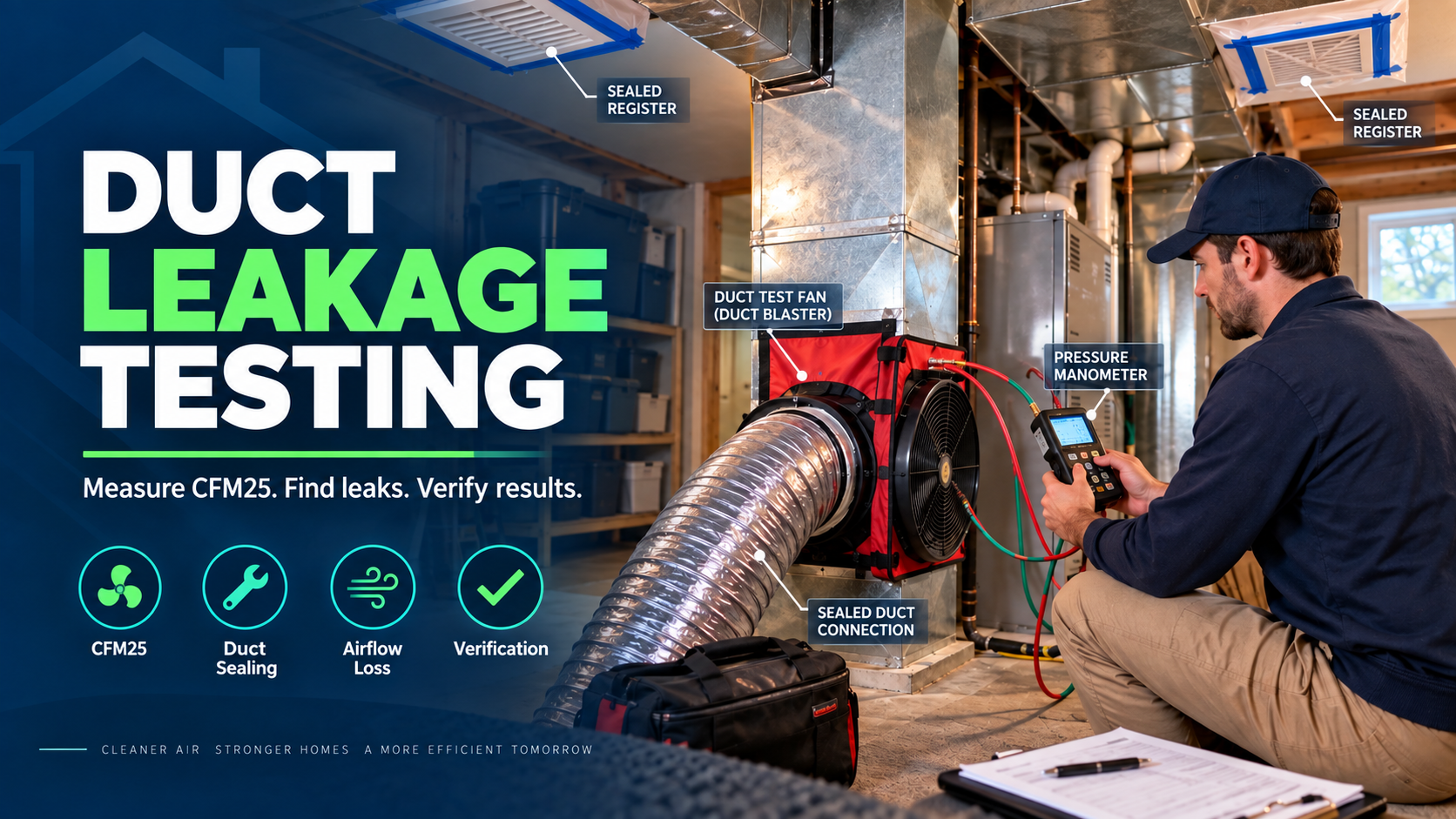
Duct leakage can waste conditioned air, create comfort problems, alter building pressures, and undermine otherwise efficient HVAC equipment. This professional guide explains duct blaster testing, CFM25, total duct leakage versus leakage to outdoors, normalized leakage calculations, current ENERGY STAR duct-leakage criteria, duct repair priorities, post-repair verification, and how duct diagnostics fit into a complete home-performance workflow.
Duct Leakage Testing Explained: CFM25, Duct Blaster Testing, Airflow Loss, and Better HVAC Performance
A high-efficiency furnace, heat pump, or air conditioner can only perform as well as the air-distribution system connected to it.
If conditioned air is escaping through disconnected joints, poorly sealed boots, damaged flex duct, leaking plenums, or cabinet seams, the HVAC equipment may be producing heating or cooling that never reaches the rooms it was intended to serve.
That is why duct leakage should not be treated as a cosmetic installation issue.
It is a measurable building-performance problem.
ENERGY STAR currently notes that, in a typical house, approximately 20% to 30% of the air moving through the duct system can be lost through leaks, holes, and poorly connected ducts. Those losses can contribute to higher utility bills and rooms that remain difficult to heat or cool.
A professional duct-leakage assessment moves the conversation away from:
“The ducts look okay.”
and toward:
“How much air is actually leaking, where is it going, and what changed after repair?”
That is the purpose of duct leakage testing.
A practical workflow is:
INSPECT → TEST → QUANTIFY → REPAIR → RETEST → VERIFY
⸻
What Is Duct Leakage?
Duct leakage is unintended airflow through openings in the HVAC air-distribution system.
Those openings may occur at:
* Supply trunk connections
* Return duct connections
* Branch takeoffs
* Flex-duct collars
* Plenums
* Air-handler cabinets
* Filter racks
* Duct boots
* Register connections
* Seams in sheet-metal ductwork
* Damaged flex duct
* Disconnected duct sections
* Building cavities improperly used as duct pathways
Not every leak has the same impact.
A small leak from a supply duct located entirely inside conditioned space may have a very different energy impact than the same leak in a 130°F attic.
Likewise, a return leak in a dusty crawlspace may introduce contaminants and unconditioned air into the HVAC system.
The diagnostic question is therefore not simply:
“Are the ducts leaking?”
It is:
“How much are they leaking, on which side of the system, and where does that leakage connect?”
⸻
Why Duct Leakage Matters
Duct systems perform two fundamental jobs:
1. Deliver conditioned air to rooms.
2. Return air to the HVAC equipment.
Leakage can disrupt both.
Supply-side leakage
When conditioned supply air escapes from ducts before reaching the occupied space, the HVAC system must operate longer to satisfy the thermostat.
If the leaking duct is outside the building enclosure—such as in an attic, crawlspace, garage, or unconditioned basement—the conditioned air may effectively be lost from the building.
Supply leakage to outside can also depressurize the occupied portion of the house because more air is being removed from the indoor pressure system than is being returned.
That pressure difference can encourage outdoor air to enter through envelope leakage.
DOE’s Building America guidance specifically notes that duct leakage can interact with building pressure and infiltration, with supply-side leakage tending to depressurize the house and return-side leakage tending to create positive pressure.
Return-side leakage
Return ducts operate under negative pressure when the blower runs.
Leaks can therefore pull air into the duct system from wherever the return duct passes.
That may include:
* Hot attics
* Cold crawlspaces
* Garages
* Dusty basements
* Wall cavities
Instead of returning conditioned room air to the equipment, the system may be pulling in air that now has to be heated, cooled, filtered, and sometimes dehumidified.
That can affect:
* Equipment load
* Comfort
* Indoor air quality
* Humidity
* Building pressure
* Delivered airflow
⸻
What Is CFM25?
One of the most common duct-leakage measurements is CFM25.
CFM means:
Cubic Feet per Minute
The number 25 refers to the test pressure:
25 Pascals
During a duct leakage test, a calibrated fan pressurizes or depressurizes the duct system to a pressure difference of 25 Pa.
The airflow required for the test fan to maintain that pressure is reported as CFM25.
DOE’s Building America Solution Center describes the basic test this way: the duct tester is operated until the duct system reaches 25 Pa, and the fan airflow necessary to maintain that pressure represents the measured duct leakage.
For example:
If the duct tester must move:
180 CFM
to maintain:
25 Pa
the measured duct leakage is:
180 CFM25
That number becomes the starting point for interpretation.
⸻
CFM25 Is Not Normal HVAC Airflow
This distinction matters.
A reading of 180 CFM25 does not mean that exactly 180 CFM is leaking while the HVAC equipment is operating normally.
The duct test intentionally creates a standardized pressure condition so different systems can be compared consistently.
Actual leakage during HVAC operation depends on:
* Operating pressure
* Leak size
* Leak location
* Supply versus return side
* Blower speed
* Filter condition
* Duct resistance
* Equipment configuration
CFM25 is therefore a standardized diagnostic measurement, not a direct statement of operating leakage under every condition.
⸻
What Is a Duct Blaster Test?
“Duct blaster” is commonly used as a generic field term for duct pressurization testing, although specific equipment names may be trademarks of their manufacturers.
The test generally uses:
* A calibrated duct-testing fan
* A digital manometer
* Pressure tubing
* A temporary connection to the duct system
* Materials to temporarily seal supply and return registers
The objective is to isolate the air-distribution system and measure leakage under controlled pressure.
The test can be performed in several ways depending on what the professional needs to know.
Two of the most important are:
1. Total duct leakage
2. Duct leakage to outdoors
These measurements are not interchangeable.
⸻
Total Duct Leakage vs. Leakage to Outdoors
Total duct leakage
A total duct leakage test measures leakage from all portions of the duct system connected to the HVAC equipment.
According to DOE’s Building America Solution Center, total duct leakage includes both supply and return ducts and can include leakage through equipment cabinets.
The result tells the professional:
How leaky is the entire duct system?
That is useful for:
* Installation quality
* Retrofit diagnostics
* Quality assurance
* Code or program verification
* Comparing pre- and post-sealing performance
But total leakage does not tell you how much leakage actually leaves the conditioned building enclosure.
That is where the second test becomes useful.
Duct leakage to outdoors
Leakage-to-outdoors testing attempts to isolate duct leakage that communicates with spaces outside the conditioned enclosure.
That can include ducts located in:
* Vented attics
* Crawlspaces
* Garages
* Unconditioned basements
* Wall cavities connected to outside
* Floor cavities connected to outside
DOE describes leakage-to-outdoors testing as requiring the house and duct system to be pressure-matched using both a duct tester and blower door. When the conditioned space is brought to essentially the same pressure as the ducts, leakage between the ducts and conditioned space is largely neutralized, allowing the remaining measured flow to represent leakage outside the conditioned enclosure.
This makes leakage-to-outdoors particularly valuable when trying to understand the energy consequences of duct leakage.
⸻
Why Leakage Location Matters
Consider two duct systems.
Both test at:
200 CFM25 total leakage
System A has almost all of its ducts inside a conditioned mechanical room.
System B has most of its ducts running through a vented attic.
The total leakage numbers may be identical.
The consequences may not be.
System B could be losing conditioned supply air directly into the attic or drawing extremely hot or cold attic air into the return system.
This is why experienced building-performance professionals do not stop at a single number.
They ask:
* Where are the ducts?
* Is the leakage supply-side or return-side?
* Is the leakage inside or outside the enclosure?
* What pressure effects does it create?
* Is the system delivering the required airflow?
Measurement becomes valuable when it is connected to building context.
⸻
Normalizing Duct Leakage by Floor Area
Raw CFM25 values can be difficult to compare between buildings of different sizes.
A common normalized metric is:
CFM25 per 100 square feet of conditioned floor area
The formula is:
CFM25 per 100 ft² = (Measured CFM25 × 100) ÷ Conditioned Floor Area
For example:
Measured duct leakage:
160 CFM25
Conditioned floor area:
2,000 ft²
Calculation:
(160 × 100) ÷ 2,000 = 8 CFM25 per 100 ft²
That normalized result allows the system to be compared with applicable program or code thresholds.
The correct denominator and compliance method should always follow the requirements of the governing program, standard, or jurisdiction.
⸻
What About Duct Leakage Percentage?
Another field metric sometimes used is:
Duct leakage percentage = measured leakage airflow ÷ system airflow × 100
For example:
Measured leakage:
120 CFM
Estimated or measured system airflow:
1,200 CFM
The simple ratio would be:
120 ÷ 1,200 × 100 = 10%
That can be useful as an explanatory or diagnostic ratio.
However, professionals should be careful.
A standardized CFM25 duct-leakage test and the actual leakage airflow under normal HVAC operating pressure are not necessarily the same value.
Therefore, a CFM25 measurement should not automatically be divided by operating airflow and presented as an exact percentage of air lost during equipment operation unless the methodology being used specifically supports that interpretation.
For compliance work, use the metric required by the applicable standard or program.
⸻
Current ENERGY STAR Duct Leakage Criteria
Duct leakage requirements are program-specific and can change, so current documentation matters.
As of September 2026, ENERGY STAR’s Single-Family New Homes program continues to reference its Revision 14 national requirements, and EPA’s policy record notes that the current post-Revision-14 policy volume was updated on June 18, 2026. Applicable program versions vary by state and project timing.
The current National Rater Field Checklist lists total duct leakage requirements that include:
Rough-in testing
The greater of:
≤ 4 CFM25 per 100 ft² of conditioned floor area
or
≤ 40 CFM25
Final testing
The greater of:
≤ 8 CFM25 per 100 ft² of conditioned floor area
or
≤ 80 CFM25
The checklist also lists a leakage-to-outdoors criterion of the greater of:
≤ 4 CFM25 per 100 ft² of conditioned floor area
or
≤ 40 CFM25
subject to the checklist’s alternatives and footnotes.
The current checklist also contains different permitted total-leakage values for certain systems with three or more ducted returns.
These numbers should not be treated as universal retrofit limits or universal building-code requirements.
They are ENERGY STAR program criteria.
Codes, utility programs, weatherization agencies, state programs, HERS protocols, and other authorities may require different testing procedures or thresholds.
Always confirm the requirement that governs the specific project.
⸻
Rough-In Testing vs. Final Testing
Duct systems can be tested at different stages of construction.
Rough-in test
A rough-in test is generally performed before finished surfaces and registers are fully installed.
Testing early can be valuable because:
* Ductwork remains accessible.
* Leaks are easier to repair.
* Failed joints can be corrected before drywall.
* Installation crews receive immediate feedback.
Finding excessive leakage at rough-in may save far more effort than discovering the same problem after the home is complete.
Final test
A final test evaluates the completed system after additional components and finished surfaces are installed according to the applicable testing protocol.
Final testing helps answer:
Did the finished HVAC air-distribution system achieve the expected leakage performance?
Both stages serve different quality-control purposes.
⸻
How a Total Duct Leakage Test Is Performed
Exact procedures should follow the applicable test standard and equipment manufacturer’s instructions, but the conceptual workflow is straightforward.
Step 1: Prepare the HVAC system
The system is turned off.
Registers, grilles, and other duct openings are temporarily sealed according to the test protocol.
Filters may need to be removed depending on test procedure.
Step 2: Connect the calibrated duct tester
The fan may be connected at:
* A return grille
* Air-handler cabinet
* Supply register
* Other appropriate system location
The goal is to create a controlled connection to the duct system.
Step 3: Connect pressure tubing
The manometer measures the pressure difference between the duct system and the test reference.
Step 4: Pressurize or depressurize the ducts
The calibrated fan is operated until the required test pressure—commonly 25 Pa—is reached.
Step 5: Record fan airflow
The airflow required to maintain 25 Pa is recorded.
That becomes the system’s:
CFM25 leakage measurement
DOE’s current duct-leakage testing guidance describes this basic procedure and identifies 25 Pa as the nominal test pressure.
⸻
How Leakage-to-Outdoors Testing Changes the Setup
Testing leakage to outside adds the building enclosure to the pressure-control process.
A blower door is used together with the duct tester.
The house is brought to approximately the same pressure as the duct system.
When those pressures are balanced, duct leaks into conditioned space contribute very little to the test.
The remaining measured leakage is primarily leakage communicating outside the conditioned boundary.
This requires careful pressure matching and trained setup.
It is not simply a second reading from the same total-leakage configuration.
⸻
What a Duct Leakage Test Does Not Tell You
A duct blaster is powerful diagnostic equipment, but one number cannot describe an entire HVAC system.
A leakage test does not by itself determine:
* Delivered airflow to each room
* Total system airflow
* Static pressure
* Blower performance
* Refrigerant charge
* Equipment capacity
* Duct sizing
* Room-by-room air balance
* Filter pressure drop
* Coil pressure drop
For example, a duct system can be extremely tight and still perform badly because the ducts are undersized.
Likewise, a system may have reasonable total airflow while some individual rooms receive too little supply air.
That is why duct leakage testing belongs within a larger HVAC diagnostic process.
⸻
Duct Leakage and Static Pressure Are Different Measurements
These two are frequently confused.
Duct leakage testing
asks:
How much air escapes through unintended openings at a standardized test pressure?
Static-pressure testing
asks:
How much resistance is the operating blower working against?
A system can have:
* High leakage and normal static pressure
* Low leakage and high static pressure
* Both problems
* Neither problem
Examples of high static-pressure causes include:
* Dirty filters
* Restrictive filters
* Undersized return ducts
* Undersized supply ducts
* Restricted coils
* Closed dampers
* Excessively compressed flex duct
* Poor fitting selection
Good HVAC commissioning may therefore involve both leakage testing and operating pressure measurements.
⸻
Duct Leakage and Manual D
Duct sealing is not a substitute for proper duct design.
ACCA currently lists ANSI/ACCA 1 Manual D – 2016 as its ANSI-recognized residential duct design manual. Manual D addresses duct sizing principles, blower performance, system operating point, pressure losses, fittings, balancing, leakage interactions, and testing and balancing.
ACCA has also conducted public review of proposed Manual D revisions in recent years, but its current public Manual D page still identifies the 2016 edition as the listed ANSI-recognized edition as of September 2026.
A strong HVAC workflow therefore separates three related questions:
Manual J: How much heating and cooling does the building require?
Manual S: Which equipment is appropriate for that load?
Manual D: How should the duct system deliver the required airflow?
Then field diagnostics answer:
Did the installed system actually perform as intended?
⸻
Common Duct Problems Found During Energy Audits
A duct leakage test becomes much more useful when combined with physical inspection.
Professionals commonly investigate:
Disconnected ducts
A completely disconnected supply branch can dump conditioned air directly into an attic or crawlspace.
Loose collars
Flex duct may appear connected while the inner liner is poorly attached beneath the outer jacket.
Plenum seams
Large leakage can occur where sheet metal or ductboard transitions connect to HVAC equipment.
Filter racks
Poorly sealed filter cabinets may allow unfiltered bypass air or leakage.
Boot-to-floor or boot-to-ceiling gaps
Air can leak around the register boot even if the duct itself is sealed.
Torn flex duct
Damage can occur from storage, pests, construction work, or age.
Crushed or compressed flex duct
This may not create a major leakage hole but can severely restrict airflow.
Panned building cavities
Wall or floor framing used as return pathways can create leakage and contamination problems.
Air-handler cabinets
Cabinet panels, access doors, wiring penetrations, and drain openings may contribute to system leakage.
⸻
How Ducts Should Be Sealed
ENERGY STAR recommends durable materials such as:
* Duct mastic
* Approved metal-backed tape
* Appropriate aerosol duct-sealing methods
ENERGY STAR specifically advises against relying on conventional cloth-backed “duct tape” for long-term duct sealing.
The sealing strategy should focus on actual leakage locations.
Important areas may include:
* Trunk seams
* Branch connections
* Takeoffs
* Elbows
* Plenum connections
* Air-handler connections
* Register boots
* Return boxes
* Flex-duct collars
Flex duct requires particular attention to the inner liner connection, not merely the outer insulation jacket.
⸻
Duct Insulation Is Not Duct Sealing
These functions are different.
Duct sealing
controls air leakage.
Duct insulation
controls conductive heat transfer through the duct surface.
A duct can be:
* Well insulated but extremely leaky
* Airtight but poorly insulated
* Both
* Neither
When ducts run through unconditioned spaces, both conditions may matter.
ENERGY STAR’s current homeowner guidance recommends sealing accessible duct leakage and insulating ducts in unconditioned areas. Its professional-contractor guidance specifically calls for insulating ducts in unconditioned areas with appropriate duct insulation and evaluating system airflow after repairs.
⸻
Why Heat Pump Retrofits Make Duct Evaluation Especially Important
A homeowner may replace an older furnace and air conditioner with a high-efficiency heat pump and assume the duct system can remain unchanged.
That assumption deserves verification.
DOE has specifically identified duct readiness as an important heat-pump retrofit issue, noting that leaky, poorly insulated, or undersized duct systems can reduce realized performance, comfort, and durability when new heat pumps are installed.
A heat-pump project should therefore consider:
* Duct leakage
* Total airflow
* Return capacity
* Supply capacity
* Static pressure
* Duct insulation
* Room-by-room delivery
* Equipment airflow requirements
Installing better equipment on a poor distribution system does not automatically create a high-performance HVAC system.
⸻
Duct Leakage Can Affect Indoor Air Quality
Return leakage can pull air from undesirable locations.
Examples include:
* Dusty crawlspaces
* Garages
* Attics
* Wall cavities
That air may carry:
* Dust
* Fibers
* Odors
* Moisture
* Outdoor contaminants
In homes with combustion appliances, pressure changes also deserve careful attention.
ENERGY STAR recommends that professional duct-improvement work include checking for backdrafting of gas- or oil-burning equipment and conducting combustion-safety testing after duct sealing where applicable.
Health and safety should always take priority over energy savings.
⸻
Test Before and After Repair
One of the strongest uses of duct leakage testing is verification.
Consider this sequence:
Before
240 CFM25
Repair work
* Seal supply trunk connections
* Reattach two flex branches
* Seal return plenum
* Seal register boots
After
110 CFM25
The contractor now has quantitative evidence that the duct system changed.
Without post-work testing, the only conclusion might be:
“We sealed the ducts.”
With testing, the conclusion becomes:
“Measured leakage changed from one verified condition to another.”
That difference matters for:
* Quality assurance
* Utility programs
* Weatherization
* Home-performance contracting
* Customer communication
* Contractor accountability
* Retrofit verification
⸻
Repair Completion Is Not the Same as Performance Verification
A WorkScope might say:
* Seal duct connections
* Repair disconnected branch
* Seal return plenum
* Insulate attic ducts
Those tasks can be checked visually.
But visual completion does not automatically prove performance.
Post-retrofit verification can include:
* Repeat CFM25 testing
* Static-pressure testing
* Total airflow measurement
* Register airflow
* Temperature split
* Room pressure testing
* Combustion-safety testing where applicable
ENERGY STAR’s professional duct-contractor guidance specifically recommends evaluating airflow after repairs are completed.
The larger building-performance principle is:
Do not stop at “work completed.” Verify the outcome.
⸻
A Professional Duct Diagnostic Workflow
A robust residential duct assessment can follow this sequence.
1. Review occupant complaints
Ask about:
* Hot rooms
* Cold rooms
* Noise
* Long run times
* Weak airflow
* Dust
* Odors
* Humidity
* High bills
Occupants often provide the first clues.
2. Inspect the entire duct system
Where accessible, inspect:
* Attics
* Basements
* Crawlspaces
* Mechanical rooms
* Supply ducts
* Return ducts
* Equipment cabinets
* Registers
ENERGY STAR recommends that professional duct contractors inspect the whole system, including attic and crawlspace sections.
3. Record duct location
Identify whether each section is:
* Inside conditioned space
* In an attic
* In a crawlspace
* In a garage
* In an unconditioned basement
Location changes the interpretation of leakage.
4. Perform duct leakage testing
Measure:
* Total CFM25
* Leakage to outdoors where required or useful
Normalize the results when needed.
5. Evaluate system airflow
Where appropriate, measure:
* Total external static pressure
* Blower airflow
* Return restrictions
* Supply restrictions
6. Develop the WorkScope
Prioritize:
* Major disconnected ducts
* Large leakage sites
* Return problems
* Damaged flex duct
* Air-handler leakage
* Register boots
* Duct insulation
7. Complete the repair
Use durable, approved materials and appropriate installation practices.
8. Retest
Repeat the diagnostic measurement.
9. Verify HVAC operation
Confirm that repairs did not create new airflow or pressure problems.
10. Document the final condition
The final report should record:
* Pre-test result
* Repairs performed
* Post-test result
* Remaining deficiencies
* Relevant safety testing
⸻
Where BPMS™ Fits Into Duct Leakage Testing
Duct diagnostics create information that often becomes fragmented across:
* Manometer photos
* Handwritten notes
* Spreadsheets
* Audit software
* Contractor proposals
* WorkScopes
* Final reports
A connected building-performance workflow can keep those pieces together.
A BPMS™ project can organize the duct assessment around:
AUDIT → DIAGNOSTIC TEST → FINDINGS → WORKSCOPE → REPAIR → RETEST → REPORT
Useful project information may include:
* Measured CFM25
* Conditioned floor area
* Duct location
* Supply/return observations
* Photos
* Equipment information
* Repair recommendations
* Pre- and post-retrofit results
BPMSField™ can support field documentation while the broader BPMS™ workflow can keep project observations, recommendations, WorkScopes, and reports associated with the building record.
The objective is not to replace professional judgment.
It is to make that judgment easier to document, communicate, and verify.
⸻
The Bigger Lesson: Measure the Distribution System
HVAC efficiency is often discussed almost entirely in terms of equipment ratings.
But the equipment is only one part of the system.
The home also depends on:
* The building envelope
* The load calculation
* The equipment selection
* The duct design
* Duct tightness
* Airflow
* Controls
* Installation quality
* Commissioning
A premium heat pump connected to a badly leaking duct system is still connected to a badly leaking duct system.
A high-efficiency furnace cannot heat a bedroom effectively if the supply branch has become disconnected.
A smart thermostat cannot repair a leaking return plenum.
Building performance works when the entire system is measured and understood.
That is why CFM25 matters.
Not because the number itself is the goal.
But because the number gives professionals a repeatable way to determine whether the duct system is behaving as intended—and whether the repair actually changed it.
Measure the leakage. Find the problem. Repair the system. Test it again.
That is how duct sealing becomes building performance rather than guesswork.
For energy auditors, HVAC contractors, weatherization agencies, utility programs, and home-performance professionals looking to connect diagnostics, WorkScopes, field documentation, and verification, explore BPMS™ at BPMSCloud.com.
Comments and Reviews
Share what you found helpful and how this article supported your work.
0.0/5from 0 reviews
No reviews yet. Be the first to share your feedback.