Blower-Door Testing for Building Performance: From CFM50 and ACH50 to Better Air-Sealing Decisions
Published 9/28/2026
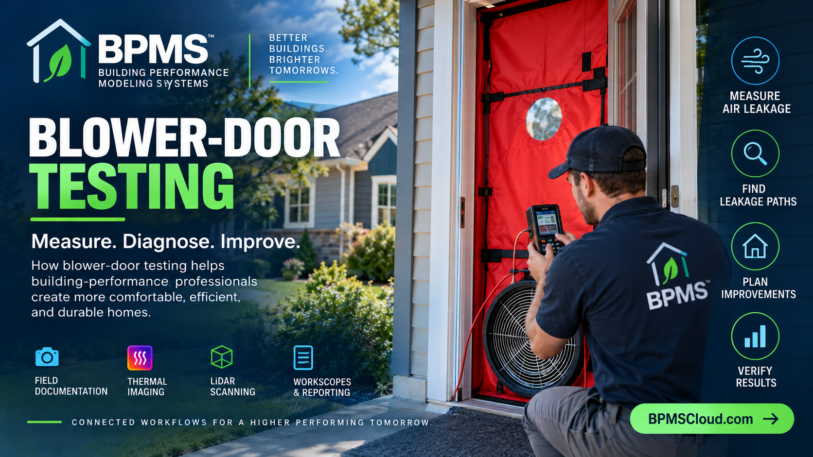
Blower-door testing turns invisible building-envelope leakage into measurable information. Learn what CFM50 and ACH50 mean, how professionals use pressure testing to investigate leakage pathways, why ventilation and combustion safety matter, and how pre- and post-work testing can strengthen weatherization and building-performance projects. Cover image URL
Blower-Door Testing for Building Performance: From CFM50 and ACH50 to Better Air-Sealing Decisions
Air leakage is one of the most important—and least visible—characteristics of a building enclosure.
A house can appear well insulated and still contain numerous pathways connecting conditioned space with attics, crawlspaces, garages, wall cavities, and the outdoors.
Those pathways can affect energy use, comfort, pressure relationships, moisture transport, ventilation planning, and overall building performance.
A blower-door test gives building-performance professionals a controlled way to quantify whole-building air leakage.
But the real value of blower-door testing is not simply producing a number.
It is turning that measurement into useful diagnostic information.
The strongest workflow is:
MEASURE → INVESTIGATE → PLAN → IMPROVE → VERIFY
What Is a Blower-Door Test?
A blower-door system typically consists of:
* An adjustable frame installed in an exterior doorway
* An airtight fabric panel
* A calibrated fan
* A digital pressure gauge or manometer
* Tubing used to measure pressure differences
The fan creates a controlled pressure difference between the building interior and outdoors.
For many residential testing procedures, measurements are commonly reported at a pressure difference of 50 Pascals, although the applicable test procedure, code, standard, or program should determine the required method.
The test allows the professional to quantify how much airflow is required to maintain the specified pressure difference.
That measurement is commonly expressed as CFM50.
Understanding CFM50
CFM50 means cubic feet per minute of airflow measured at a 50-Pascal pressure difference.
For example, if a blower-door test reports:
1,800 CFM50
the calibrated fan is moving approximately 1,800 cubic feet of air per minute to maintain the test pressure under the applicable test conditions.
In general, when comparing the same building under comparable test conditions, a lower CFM50 after properly executed air-sealing work indicates a reduction in measured whole-building leakage.
But CFM50 alone does not account for building volume.
A 1,800-CFM50 result has a different meaning in a small home than it does in a very large home.
That is one reason ACH50 is also widely used.
What Is ACH50?
ACH50 means air changes per hour at a 50-Pascal pressure difference.
It normalizes the measured airflow relative to the building volume.
A commonly used calculation is:
ACH50 = \frac{CFM50 \times 60}{Building\ Volume}
where:
* CFM50 = measured airflow at 50 Pa
* 60 = minutes per hour
* Building Volume = applicable tested volume in cubic feet
Consider a simplified example:
CFM50 = 1,800
Building volume = 18,000 ft³
Then:
ACH50 = \frac{1,800 \times 60}{18,000}
ACH50 = 6.0
The result would be 6 ACH50.
This does not mean the building naturally exchanges its entire air volume six times every hour during normal operation.
ACH50 describes leakage under the artificial pressure conditions of the test. Estimating natural infiltration involves additional assumptions and methods.
The Number Is Only the Beginning
A blower-door result tells the professional how much leakage is measured under the test condition.
It does not automatically tell the professional where the leakage is located.
That requires investigation.
With the building under an appropriate pressure condition, leakage pathways may sometimes be investigated using methods such as:
* Hand or skin sensation where appropriate
* Smoke or other approved visualization methods
* Pressure diagnostics
* Infrared thermography when temperature conditions are suitable
* Visual inspection
* Zone-pressure diagnostics
* Other accepted building-science techniques
Testing and diagnostic methods should be performed according to applicable procedures and safety requirements.
Where Air Leakage Often Occurs
Every building is different, but common leakage locations can include:
* Attic penetrations
* Plumbing penetrations
* Electrical penetrations
* Recessed fixtures
* Top plates
* Rim and band joists
* Basement-to-house connections
* Crawlspace boundaries
* Exterior doors
* Window assemblies
* Mechanical chases
* Dropped soffits
* Duct penetrations
* Fireplace assemblies
* Access hatches
* Attached-garage interfaces
A useful diagnostic process distinguishes between leakage that is easy to see and leakage hidden within interconnected building cavities.
Thermal Imaging Can Add Context
Thermal imaging can be particularly useful during some blower-door investigations.
When there is an adequate indoor-to-outdoor temperature difference and suitable environmental conditions, infrared imagery may help reveal thermal patterns associated with air movement or insulation anomalies.
For example, depressurization can sometimes accentuate temperature patterns where outdoor or adjacent-zone air is being drawn through enclosure pathways.
However, an infrared camera does not directly “see air leakage.”
It measures infrared radiation associated with surface temperatures.
Interpreting thermal images therefore requires understanding:
* Temperature difference
* Surface emissivity
* Reflections
* Solar loading
* Wind
* Moisture
* Building materials
* HVAC operation
* Test conditions
Thermal imagery should be treated as diagnostic evidence requiring interpretation—not automatic proof of a specific defect.
Blower-Door Testing and Air Sealing
Once significant leakage pathways are identified, the project team can develop a targeted air-sealing strategy.
That is preferable to treating air sealing as simply applying sealant wherever a gap is visible.
The objective is to understand the building’s pressure and enclosure boundaries.
High-value opportunities may involve connections between conditioned space and:
* Attics
* Crawlspaces
* Basements
* Garages
* Exterior walls
* Mechanical chases
* Other unconditioned or indirectly connected zones
A WorkScope can then document:
What should be sealed → Where it is located → Appropriate material or method → Responsible trade → Verification requirement
Actual materials and installation methods should be selected for the specific assembly and applicable fire, durability, moisture, code, and manufacturer requirements.
Air Sealing and Insulation Are Related—but Different
Air barriers and thermal insulation perform different functions.
Insulation primarily resists heat transfer through an assembly.
An air-control layer limits uncontrolled airflow.
Some materials can contribute to both functions when properly designed and installed, but insulation alone should not automatically be assumed to provide an effective air barrier.
This distinction is especially important in attics and framed assemblies.
For example, adding insulation over significant bypasses without first addressing appropriate air-leakage pathways may leave important enclosure problems unresolved.
A coordinated enclosure strategy evaluates both:
AIR CONTROL + THERMAL CONTROL
Do Not Chase the Lowest ACH50 Without Context
A lower leakage result is not automatically better under every circumstance.
Buildings need intentional strategies for:
* Outdoor-air ventilation
* Moisture management
* Combustion safety
* Exhaust systems
* Pressure relationships
* Indoor environmental quality
As uncontrolled leakage is reduced, planned ventilation can become increasingly important.
Applicable ventilation standards, codes, weatherization programs, and project specifications may establish requirements based on building type, climate, occupancy, and other conditions.
Professionals should use the requirements applicable to the specific project rather than relying on a universal ACH50 target.
Combustion Safety Must Be Considered
Air sealing can alter pressure relationships in a building.
Buildings containing combustion appliances deserve particular attention because changes in enclosure leakage, exhaust operation, or mechanical-system pressures may affect combustion-zone conditions.
Applicable combustion-safety procedures can vary by fuel type, appliance category, program, jurisdiction, and professional standard.
Where combustion appliances are present, qualified professionals should follow the required testing and safety procedures for the project.
Air sealing should never be treated solely as an energy calculation.
Energy efficiency, ventilation, moisture management, and safety must work together.
Pre- and Post-Work Testing Creates Measurable Verification
One of the strongest uses of blower-door testing is establishing a baseline before work and measuring again afterward.
Consider a simplified example:
Pre-work: 2,600 CFM50
Post-work: 1,950 CFM50
The measured reduction would be:
2,600 - 1,950 = 650\ CFM50
or a 25% reduction in measured CFM50 under comparable test conditions.
That provides something more useful than:
“We sealed the attic.”
It provides measured evidence that the building’s tested leakage changed.
Care should still be taken to maintain comparable test configuration and follow the applicable procedure when comparing results.
Blower-Door Results Can Inform Other Building-Performance Decisions
Air leakage information can influence more than weatherization.
Depending on the methodology and project, it may contribute to:
* Energy modeling
* HVAC load calculations
* Ventilation evaluation
* Home-performance assessments
* Energy-code documentation
* Home Energy Score workflows
* Retrofit planning
* Quality assurance
* Utility-program documentation
The exact use of blower-door data should follow the requirements of the relevant calculation method, standard, code, or program.
Documentation Matters
A professional blower-door record should contain enough information to understand the test later.
Depending on the applicable procedure, useful documentation may include:
* Building identification
* Date and time
* Technician
* Equipment information
* Test configuration
* Indoor/outdoor conditions where required
* Building volume used
* CFM50
* ACH50
* Baseline pressure information
* Test direction
* Relevant photographs
* Diagnostic observations
* Pre- or post-work designation
* Applicable program information
* Notes about unusual conditions
Good documentation makes the result useful beyond the moment when the test was performed.
From Measurement to WorkScope
The diagnostic process becomes particularly valuable when measurements lead directly to actionable project information.
Imagine an auditor identifies:
* Significant attic bypasses
* Leakage at a plumbing chase
* An unsealed attic access
* Rim-joist leakage
* Leakage around mechanical penetrations
Instead of placing those findings in unrelated notes, the project can move through a structured sequence:
FIELD FINDING
↓
DIAGNOSTIC EVIDENCE
↓
RECOMMENDATION
↓
WORKSCOPE
↓
INSTALLATION
↓
POST-WORK TEST
↓
REPORT
That is where building-performance data becomes operational.
How BPMS™ Can Support a Connected Diagnostic Workflow
BPMS™ — Building Performance Modeling Systems™ — is designed around connecting building information throughout the project lifecycle.
A blower-door result does not have to exist as an isolated number.
Within a broader BPMS™ workflow, building-performance professionals can organize information associated with:
* Energy audits
* Building characteristics
* Diagnostic measurements
* Field photographs
* Thermal imagery
* Recommendations
* WorkScopes
* Proposals
* Project documentation
* Reports
BPMSField™ can support collection of project evidence in the field.
BPMS Thermal™ can keep thermal documentation associated with the corresponding building project.
The broader BPMS™ platform can help carry findings into recommendations, WorkScopes, and reporting.
The purpose is not to replace the professional performing the diagnostic test.
It is to strengthen the information chain around that test.
A Professional Blower-Door Workflow
A useful workflow can be summarized in eight stages:
1. Prepare
Follow the applicable test procedure and establish the required building configuration.
2. Measure
Perform the blower-door test and record the required leakage data.
3. Calculate
Determine metrics such as ACH50 when appropriate and when the necessary building-volume information is available.
4. Investigate
Use appropriate diagnostic techniques to locate significant leakage pathways.
5. Document
Capture observations, measurements, photographs, and thermal evidence where useful.
6. Plan
Translate findings into prioritized air-sealing and enclosure recommendations.
7. Improve
Complete the approved WorkScope using appropriate materials and installation practices.
8. Verify
Where required or useful, repeat testing under comparable conditions and document the result.
Measure Before You Improve
Blower-door testing illustrates one of the most important principles in building science:
If performance can be measured, improvement can be evaluated rather than assumed.
The blower door does more than produce CFM50.
Combined with professional diagnostics, it can help reveal how the enclosure behaves.
Combined with a WorkScope, it can guide action.
Combined with post-work testing, it can help verify change.
And combined with good documentation, it creates a building-performance record that can remain useful long after the fan is removed from the doorway.
For energy auditors, weatherization professionals, HERS raters, HVAC contractors, Home Energy Score assessors, and building-science organizations, that creates a stronger progression:
Measure what exists. Diagnose what matters. Improve intelligently. Verify what changed.
Explore BPMSCloud.com to learn more about connected building-performance workflows with BPMS™.
Comments and Reviews
Share what you found helpful and how this article supported your work.
0.0/5from 0 reviews
No reviews yet. Be the first to share your feedback.