Blower Door Testing Explained: CFM50, ACH50, Air Leakage & Building Performance
Published 9/11/2026
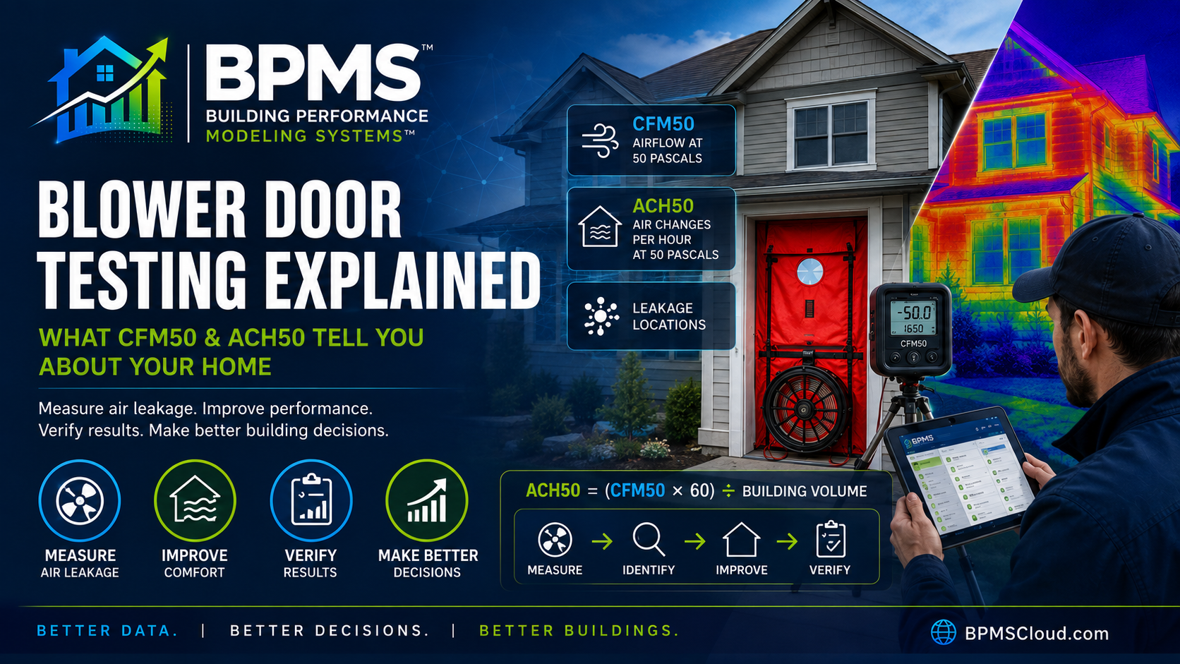
Learn how blower door testing measures building-envelope air leakage, what CFM50 and ACH50 mean, how to calculate ACH50, and how energy auditors and building-performance professionals can use blower door results alongside thermal imaging, field observations, HVAC information, and other diagnostics to make better-informed retrofit decisions.
Blower Door Testing Explained: CFM50, ACH50, Air Leakage & Building Performance
Every building exchanges air with the outdoors.
Some of that exchange is intentional, such as mechanical ventilation. Some occurs through doors and windows when occupants open them. But a significant amount can also occur unintentionally through cracks, joints, penetrations, transitions, and other openings in the building enclosure.
Those uncontrolled leakage pathways can influence heating and cooling loads, occupant comfort, moisture transport, HVAC operation, ventilation strategies, and overall building performance.
The challenge is that air leakage is difficult to quantify through visual inspection alone.
A building can appear well constructed and still contain numerous interconnected leakage pathways hidden behind finishes, around framing transitions, through mechanical penetrations, or between conditioned and unconditioned spaces.
This is where blower door testing becomes valuable.
A blower door allows qualified building-performance professionals to place a building under a controlled pressure difference and measure the airflow required to maintain that pressure.
Instead of simply saying:
“This house seems drafty.”
the professional can obtain a quantitative measurement of enclosure leakage.
Two terms frequently encountered in residential blower door testing are:
CFM50 and ACH50.
Understanding what these measurements represent—and what they do not represent—is fundamental to using blower door data correctly.
⸻
What Is a Blower Door Test?
A blower door is a diagnostic system generally consisting of:
* An adjustable frame
* An airtight fabric panel
* A calibrated variable-speed fan
* Pressure tubing
* A digital pressure gauge or manometer
* Appropriate flow rings or fan configurations
The system is temporarily installed in an exterior doorway.
With the building prepared according to the applicable testing procedure, the calibrated fan is operated to create a pressure difference between the building interior and outdoors.
For many residential applications, a commonly reported test condition is 50 Pascals.
The equipment measures how much airflow is required to maintain that pressure difference.
That airflow provides a quantitative indication of the building enclosure’s leakage under the test condition.
⸻
Why 50 Pascals?
A Pascal is a unit of pressure.
Fifty Pascals is a relatively small pressure in everyday terms, but it is large enough to create a repeatable diagnostic condition across a building and make enclosure leakage measurable with calibrated equipment.
The test pressure should not be confused with ordinary natural operating pressure.
A home does not normally remain at a constant 50-Pascal indoor-outdoor pressure difference.
Natural infiltration is driven by changing forces including:
* Wind
* Indoor-outdoor temperature difference
* Stack effect
* Mechanical exhaust
* Supply and return airflow imbalances
* Building height
* Shelter and exposure
A blower door intentionally creates a standardized diagnostic condition.
This distinction is important:
CFM50 is measured airflow at the blower door test pressure—not the amount of outdoor air naturally entering the building every minute during normal operation.
⸻
What Does CFM50 Mean?
CFM50 means:
Cubic Feet per Minute at 50 Pascals.
Suppose a blower door test produces:
1,650 CFM50
This means the calibrated fan is moving approximately 1,650 cubic feet of air per minute to maintain the specified 50-Pascal pressure difference under the test configuration.
Generally, if two otherwise comparable buildings have the same size and testing conditions, the building requiring greater airflow to maintain the pressure difference has greater enclosure leakage.
However, CFM50 by itself has an important limitation:
It does not account for building size.
A 1,650-CFM50 result can mean something very different for a small house than for a much larger building.
That is one reason ACH50 is commonly used.
⸻
What Does ACH50 Mean?
ACH50 stands for:
Air Changes per Hour at 50 Pascals.
ACH50 normalizes the measured blower door airflow to the building volume.
Conceptually, it answers:
At the 50-Pascal test condition, how many building-volume equivalents of air would move through the enclosure in one hour?
The calculation is:
ACH50 = (CFM50 × 60) ÷ Building Volume
where:
* CFM50 = measured cubic feet per minute at 50 Pascals
* 60 = minutes per hour
* Building Volume = applicable interior volume in cubic feet
⸻
ACH50 Calculation Example
Assume a house has:
CFM50 = 1,650
and an applicable building volume of:
19,000 cubic feet
First convert the measured airflow from cubic feet per minute to cubic feet per hour:
1,650 × 60 = 99,000 cubic feet per hour
Then divide by the building volume:
99,000 ÷ 19,000 = 5.21
The result is approximately:
5.2 ACH50
Again, this does not mean the home naturally experiences 5.2 complete air changes every hour under normal weather conditions.
It describes leakage relative to building volume at the standardized blower door test condition.
⸻
CFM50 vs. ACH50: Why Both Matter
CFM50 and ACH50 describe related but different aspects of the test.
CFM50
CFM50 reports the measured airflow required to maintain the test pressure.
It is especially useful as a direct measurement of the blower door test and can be valuable when comparing the same building before and after air-sealing work.
ACH50
ACH50 accounts for building volume.
This makes it useful when evaluating leakage intensity across buildings of different sizes or when a program, standard, or code expresses an airtightness requirement in air changes per hour at 50 Pascals.
Neither metric should automatically be interpreted without context.
The appropriate interpretation depends on the building, climate, test protocol, project objectives, applicable program requirements, code edition, ventilation strategy, and other factors.
⸻
Where Does Air Leakage Occur?
A building enclosure contains many potential leakage pathways.
Common areas worth investigating can include:
* Attic access panels
* Plumbing penetrations
* Electrical penetrations
* Recessed fixtures
* Top plates
* Bottom plates
* Rim and band joists
* Window and door rough openings
* Fireplace assemblies
* Mechanical penetrations
* Duct chases
* Dropped soffits
* Plumbing chases
* Kneewalls
* Attached garage transitions
* Foundation-to-framing connections
* Cantilevers
* Utility penetrations
Some leakage pathways are easy to see.
Others may be concealed inside assemblies.
The blower door tells the professional how much leakage exists under the test condition.
Additional diagnostic techniques can help investigate where that leakage is occurring.
⸻
Finding Leakage While the Blower Door Is Operating
One of the most useful aspects of blower door testing is that the controlled pressure difference can make leakage pathways easier to investigate.
Depending on the procedure and conditions, professionals may use techniques such as:
* Physical inspection
* Hand detection where appropriate
* Smoke visualization using suitable methods
* Infrared thermography under appropriate environmental conditions
* Pressure diagnostics
* Zone testing
* Other approved building-science diagnostic procedures
These methods should be selected and interpreted by qualified professionals according to the purpose of the assessment and applicable safety procedures.
⸻
Blower Door Testing and Thermal Imaging
Blower door testing and thermal imaging can be particularly complementary.
A blower door creates a controlled pressure difference.
Thermal imaging visualizes apparent surface-temperature patterns.
Under suitable indoor-outdoor temperature and environmental conditions, operating a blower door may make some air-movement-related thermal patterns more apparent.
For example, incoming outdoor air may alter surface temperatures near leakage pathways.
However, thermal imagery requires careful interpretation.
A temperature pattern does not automatically prove air leakage.
Similar patterns can potentially result from:
* Missing or inconsistent insulation
* Thermal bridging
* Solar loading
* Moisture
* HVAC operation
* Material differences
* Surface emissivity
* Reflections
* Other environmental conditions
The strongest diagnostic conclusions generally come from combining multiple forms of evidence rather than relying on a single image.
Within a connected workflow, BPMS Thermal™ can help associate thermal documentation with the broader building-performance project.
⸻
Why Air Leakage Matters
Air leakage is not simply an energy issue.
It can influence several aspects of building performance.
Heating and Cooling Loads
Uncontrolled outdoor air entering a building may need to be heated, cooled, or dehumidified.
Reducing excessive enclosure leakage can therefore reduce infiltration-related loads.
The magnitude of potential savings depends on climate, leakage reduction, HVAC efficiency, operating conditions, occupancy, and many other factors.
⸻
Comfort
Air leakage can contribute to:
* Drafts
* Cold surfaces
* Uneven room temperatures
* Localized discomfort
* Greater sensitivity to wind and outdoor conditions
Air sealing can sometimes produce comfort improvements even when the energy savings alone do not fully communicate the benefit.
⸻
Moisture Transport
Air movement can transport significant amounts of water vapor through building assemblies.
Depending on climate, season, enclosure design, and indoor moisture conditions, uncontrolled airflow can contribute to condensation or durability concerns.
Air sealing therefore plays an important role in both energy performance and moisture management.
⸻
HVAC Performance
Building leakage contributes to heating and cooling demand.
If substantial enclosure improvements are made, the building’s load characteristics may change.
For major retrofit projects, HVAC sizing and performance should therefore be evaluated using appropriate procedures rather than assuming the existing equipment remains correctly sized.
⸻
Blower Door Testing Before Air Sealing
A pre-retrofit blower door test can establish a baseline.
For example:
Before air sealing: 2,600 CFM50
That number provides a measurable starting point.
The professional can then investigate leakage pathways and develop an air-sealing strategy based on the building’s construction and project objectives.
⸻
Blower Door Testing After Air Sealing
After appropriate air-sealing work is completed, another test can quantify the change.
Suppose the post-work result is:
1,850 CFM50
The measured reduction would be:
2,600 − 1,850 = 750 CFM50
The percentage reduction relative to the original result would be approximately:
750 ÷ 2,600 × 100 = 28.8%
This provides objective evidence that measured enclosure leakage decreased under the test conditions.
It does not, by itself, establish a precise percentage reduction in annual energy consumption.
Energy savings depend on additional variables including weather, equipment efficiency, occupant behavior, ventilation, and building characteristics.
⸻
Airtightness and Ventilation Must Be Considered Together
Reducing uncontrolled air leakage can improve building performance.
But:
A tighter building is not the same thing as a properly ventilated building.
Air leakage is uncontrolled.
Mechanical ventilation is intentional and designed.
As buildings become tighter, ventilation requirements and indoor-air-quality considerations become increasingly important.
Applicable ventilation requirements may depend on factors such as:
* Jurisdiction
* Building code
* Program requirements
* Building type
* Occupancy
* Applicable standard or edition
* Existing mechanical systems
Professionals should evaluate ventilation according to the requirements governing the specific project.
⸻
Combustion Safety Also Matters
Air sealing can alter building pressure relationships.
Buildings containing atmospherically vented or other combustion appliances may require appropriate combustion-safety evaluation before, during, or after enclosure work depending on the applicable program, standard, equipment, and project scope.
Professionals should follow the relevant safety procedures and requirements rather than assuming an airtightness target can be pursued independently of the rest of the building.
This illustrates a central principle of building science:
The building operates as a system.
Changes to one part can affect another.
⸻
Blower Door Testing in Energy Audits
For an energy auditor, blower door testing can provide a quantitative foundation for enclosure analysis.
Rather than documenting only:
“Air leakage observed around attic penetrations.”
the audit can potentially include:
* Measured CFM50
* Calculated ACH50
* Building volume
* Test conditions
* Equipment information
* Leakage observations
* Photographs
* Thermal documentation
* Recommended air-sealing opportunities
* Pre- and post-work results when applicable
This creates a more defensible and useful project record.
⸻
Connecting Blower Door Data With the Rest of the Building
A blower door result becomes even more useful when it is evaluated alongside other building information.
That can include:
Building geometry
How large is the enclosure?
Insulation
What thermal resistance and installation conditions exist?
Thermal imaging
Where are temperature patterns worth investigating?
HVAC
What equipment serves the building?
Duct testing
Is conditioned air being lost through the distribution system?
Energy use
How has the building actually been consuming energy?
Photographs and observations
What conditions were documented in the field?
Ventilation
How is intentional outdoor air provided?
When these data remain connected, professionals can move beyond isolated test results toward a more complete understanding of building performance.
⸻
Bringing Blower Door Testing Into BPMS™
BPMS™ — Building Performance Modeling Systems™ is designed around the idea that building-performance information should remain connected throughout the project.
Blower door measurements can become part of a broader project record alongside:
* Building characteristics
* Envelope information
* Field photographs
* Thermal documentation
* HVAC information
* Duct leakage information
* Energy-use data
* Recommendations
* WorkScopes
* Project reporting
BPMSField™ can support field documentation, while BPMS Thermal™ can help organize thermal-imaging information associated with the assessment.
The objective is not simply to store a CFM50 number.
It is to preserve the context surrounding that number.
⸻
From Measurement to Action
The strongest blower door workflow follows a logical progression:
MEASURE → IDENTIFY → IMPROVE → VERIFY
Measure
Establish the building’s leakage under defined test conditions.
Identify
Investigate significant leakage pathways using appropriate diagnostic techniques.
Improve
Develop and implement appropriate air-sealing measures while considering ventilation, moisture, HVAC, combustion safety, and applicable requirements.
Verify
Repeat appropriate testing to determine whether the work achieved the intended measurable improvement.
That final verification step is important.
Building performance should not rely entirely on assumptions when measurable results are available.
⸻
What a Blower Door Test Cannot Tell You by Itself
Blower door testing is powerful, but it is not a complete energy audit by itself.
A blower door result alone does not tell you:
* Exactly where every leak is located
* The condition of all insulation
* HVAC efficiency
* Duct leakage
* Annual energy consumption
* Moisture content
* Combustion safety
* Indoor air quality
* Exact annual savings from air sealing
* The complete retrofit strategy
Those questions require additional information.
That is why building diagnostics work best as part of a comprehensive assessment.
⸻
Better Data Creates Better Building Decisions
A blower door turns something largely invisible—building air leakage—into measurable information.
CFM50 tells us the airflow required to maintain the test pressure.
ACH50 relates that airflow to the building’s volume.
Diagnostic investigation can help locate important leakage pathways.
Air sealing can address appropriate opportunities.
Post-work testing can verify measurable improvement.
And when blower door results are connected with thermal imaging, HVAC information, building geometry, energy-use history, photographs, and other diagnostic information, professionals gain a much richer understanding of the building.
The objective is not simply to make a building tighter.
The objective is to make informed improvements that support energy performance, comfort, durability, indoor environmental quality, and appropriate building operation.
That is what building performance is ultimately about.
Bring Your Building-Performance Data Together
BPMS™ helps building-performance professionals organize project information across field documentation, diagnostics, building characteristics, recommendations, WorkScopes, and reporting.
Whether you’re an energy auditor, HVAC contractor, HERS rater, weatherization professional, builder, or home-performance contractor, a connected workflow can make it easier to move from measurement to meaningful action.
Measure. Understand. Improve. Verify.
Better Data. Better Decisions. Better Buildings.
Explore BPMS™ — Building Performance Modeling Systems™ at BPMSCloud.com.
Comments and Reviews
Share what you found helpful and how this article supported your work.
0.0/5from 0 reviews
No reviews yet. Be the first to share your feedback.